With the rapid growth of renewable energy, energy storage systems, and smart grids, power conversion and inverter control have become the core of the modern energy ecosystem. Inverters must efficiently and stably convert DC power into AC power while maintaining precise synchronization with the grid. In this process, crystal oscillators play an irreplaceable role.
Key roles of crystal oscillators in power conversion and inverter control include:
Frequency Stability: Inverter control chips rely on crystal oscillators to provide accurate clock signals, ensuring the output AC frequency (50Hz/60Hz) matches the grid precisely.
Phase Synchronization: For grid-connected operations, oscillators provide reference signals for phase detection and synchronization, preventing power quality issues or equipment damage.
Data Communication: Within EMS and BMS, crystal oscillators ensure accurate timing for protocols such as CAN, RS485, and Ethernet, enabling efficient data exchange.
Power Optimization: Oscillators support microcontrollers in achieving fast and stable PWM control, improving conversion efficiency and reducing energy loss.
Future Trends
As renewable energy and smart grid technologies continue to evolve, inverters and energy storage systems demand more advanced oscillator solutions:
High-Precision TCXO/OCXO: Ensuring frequency stability under temperature variations and long-term operation.
Wide-Temperature and High-Reliability Packages: Designed for outdoor and harsh environments.
Low-Power Oscillators: Suitable for distributed energy storage and microgrid applications.
Crystal oscillators are not only the “hidden cornerstone” of power conversion and inverter control but also a key enabler for the safe and efficient operation of future energy systems.
1. Technological Breakthrough: 3500nits Brightness, Built for Outdoor Excellence
In the outdoor LED display industry, brightness is one of the most critical factors influencing visibility. Currently, most COB modules on the market offer 2000–3000nits for outdoor use—adequate for basic sunlight readability, but not always enough to maintain vivid clarity under extreme lighting. CNLC’s latest COB P1.25 high-brightness module, powered by advanced packaging techniques and refined optical design, has achieved 3500nits brightness and passed rigorous outdoor performance certifications. This significant leap ensures exceptional visibility even under intense midday sunlight, while maintaining vivid colors and fine details in cloudy, dusk, or backlit conditions—delivering an elevated visual experience for outdoor digital displays.
2. COB Advantages & Trends in Outdoor Applications
All-Day Readability High brightness combined with high contrast and anti-glare treatment ensures clear and sharp visuals under varying outdoor lighting conditions, from early morning to late evening.
Comprehensive Protection for Harsh Environments COB’s fully integrated packaging eliminates exposed lamp beads, significantly improving dust-proof, water-resistant, and impact-resistant performance—ideal for humid, dusty, and high-contact outdoor locations.
Breaking Boundaries for Ultra-Fine Outdoor Pitch Previously, pitches below P1.5 were largely limited to indoor environments. With 3500nits brightness, the P1.25 COB module brings ultra-fine image quality to outdoor settings, ideal for close-up viewing and high-definition advertising.
Longer Lifespan & Lower Maintenance Robust packaging protects chips from oxidation, static, and mechanical damage, while optimized thermal management ensures long-term stable performance in outdoor high-brightness operations, reducing maintenance and operating costs.
3. CNLC’s Outdoor-Focused R&D Direction
Pushing Brightness Boundaries Continue advancing COB brightness while maintaining efficiency and durability, meeting the demands of extreme lighting environments in high-end outdoor projects.
Efficient Thermal Management Develop next-generation cooling solutions to ensure stable operation and extended lifespan during prolonged high-brightness outdoor use.
Expanding Application Scenarios Drive COB adoption in outdoor billboards, smart city information displays, transportation hubs, retail storefronts, and sports stadiums.
4. Conclusion
The 3500nits COB P1.25 is not just a leap in brightness—it’s a milestone in ultra-fine outdoor LED display technology. It perfectly integrates high-definition image quality with all-weather visibility, setting a new standard for premium outdoor displays. With the ongoing evolution of COB packaging technology, the next 3–5 years will see high-brightness, ultra-fine, fully protected outdoor COB displays become the market mainstream—ushering the LED display industry into a new era.
CNLC remains committed to driving innovation in outdoor display technology, delivering high-performance, reliable, and visually stunning solutions for clients worldwide.
Every FIFA World Cup is more than a football tournament—it is also a global marketing festival. In 2026, the World Cup will be jointly hosted by the United States, Canada, and Mexico, marking the largest edition in history with 48 teams and 16 host cities. For sponsors, cities, and event organizers, this means massive demand for outdoor advertising displays that can deliver impact, reliability, and innovation.
2. Our Experience at Qatar 2022
At the 2022 World Cup in Qatar, CNLC successfully delivered dynamic light boxes that created a vibrant city atmosphere and amplified sponsor visibility. These projects proved our capability to provide customized, large-scale advertising solutions for world-class events.
3. Expanding Beyond Dynamic Light Boxes
Building on our success in 2022, CNLC now offers a comprehensive portfolio of outdoor advertising products suitable for World Cup 2026 projects:
LED Billboards – High-brightness, weatherproof large displays for stadiums, highways, and fan zones.
LED Totems – Stylish vertical displays for streets, commercial districts, and public plazas.
LCD Digital Displays – Ultra-clear, high-definition signage for transport hubs, retail areas, and sponsor activations.
Dynamic Light Boxes – Dynamic illuminated signs that enhance atmosphere and attract crowds.
With these solutions, we support cities and brands in building a multi-layered advertising ecosystem that maximizes visibility during the World Cup.
Comprehensive outdoor advertising solutions for global events
4. Opportunities for World Cup 2026 Host Cities
From New York and Los Angeles to Toronto and Mexico City, every host city will face unique advertising challenges and opportunities. CNLC products are designed to meet these needs:
High brightness and clarity for both daytime and nighttime visibility.
IP-rated, weatherproof structures to withstand outdoor conditions.
Energy-efficient LED and LCD technology supporting sustainability goals.
Customizable formats to match stadium, fan zone, and city branding requirements.
5. CNLC: Ready for World Cup 2026 Projects
With over 18 years of experience in outdoor advertising solutions, CNLC is ready to partner with event organizers, sponsors, and municipalities to deliver innovative, reliable, and visually striking displays for the 2026 FIFA World Cup.
6. Conclusion
The countdown to FIFA World Cup 2026 has already begun. Cities and sponsors aiming to capture global attention must invest in advanced advertising technologies. CNLC stands ready with LED billboards, LED totems, LCD displays, and dynamic light boxes, helping transform urban landscapes into unforgettable World Cup experiences.
👉Contact CNLC today to discuss customized outdoor advertising solutions for FIFA World Cup 2026.
SMD, MIP, and COB: The Three Main LED Packaging Technologies You Should Know
In the LED display industry, packaging technology determines display performance, durability, and application range. Today, SMD (Surface Mounted Device), MIP (Mini LED in Package), and COB (Chip-on-Board) are the three most common technologies. Each has its strengths and ideal application scenarios. This article will help you understand their differences and choose the best option for your project.
1. SMD (Surface Mounted Device)
Technology SMD LEDs are made by packaging red, green, and blue chips into a single LED unit, which is then mounted directly onto the PCB surface.
Advantages
Mature technology with lower manufacturing costs
Wide pixel pitch range, from P1.25 for indoor to P10 for outdoor
Easy maintenance—individual LED modules can be replaced
Limitations
Exposed surface makes it more vulnerable to impact or damage
Higher precision required for small pixel pitch
Best Applications Outdoor billboards, rental stage screens, indoor conference displays, and other medium-to-large pixel pitch projects.
2. MIP (Mini LED in Package)
Technology MIP bridges the gap between SMD and COB. Mini LED chips are packaged individually before being mounted onto the PCB, offering improved performance without fully integrating into the board like COB.
Advantages
Supports smaller pixel pitches (P0.x level)
Higher production yield compared to COB
Stable brightness and color uniformity
Easy to replace individual LEDs
Limitations
Higher cost than SMD
Technology still evolving
Best Applications Premium indoor displays, broadcast studios, control rooms, and fine-pitch commercial screens.
3. COB (Chip-on-Board)
Technology COB involves mounting bare LED chips directly onto the PCB and covering them with a protective layer, eliminating the traditional LED lamp package.
Advantages
Flat, seamless surface for better protection against dust, moisture, and impact
Ultra-high density, supporting pixel pitches as small as P0.4
Superior heat dissipation and extended lifespan
Higher durability for public environments
Limitations
More expensive to produce
Repair requires replacing the entire module
Best Applications High-end control rooms, security monitoring centers, banking institutions, and flagship retail displays.
4. Quick Comparison Table
Feature
SMD
MIP
COB
Cost
Low
Medium
High
Protection
Medium
Medium-High
High
Maintenance
Easy
Easy
Difficult
Pixel Pitch Range
≥P1.25
≥P0.7
≥P0.4
Brightness
High
High
Medium-High
Applications
Indoor + Outdoor
Indoor High-End
Indoor Ultra High-End
5. Market Trends
SMD will remain dominant in outdoor and large pixel pitch markets.
MIP is likely to become the preferred choice for small pixel pitch commercial displays.
COB will grow rapidly in ultra-fine pitch and high-protection displays.
As Mini LED and Micro LED technology continues to advance, we can expect higher resolution, lower power consumption, and improved durability across all display types. Choosing the right packaging technology will help balance cost, performance, and maintenance needs for your project.
Why Choose CNLC?
As a professional LED display manufacturer, CNLC offers SMD, MIP, and COB solutions for indoor and outdoor applications, from commercial advertising to control room installations. Whether you provide your own LED screen or require a complete turnkey solution, we can deliver custom manufacturing, integration, and after-sales support to ensure your project stands out in the market.
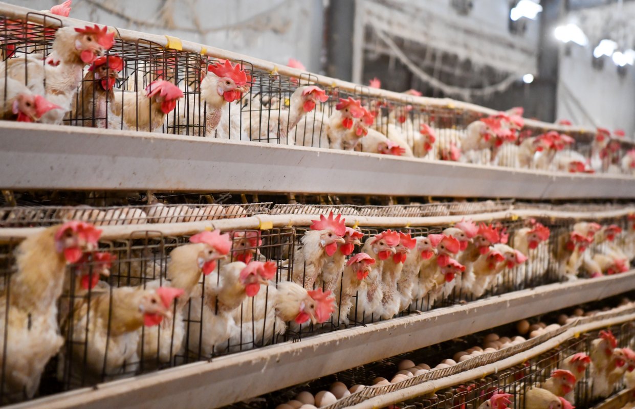
With a growing global population and increasing consumer demand for high-quality protein, the broiler farming industry is undergoing unprecedented change. As an efficient and sustainable production mode, large-scale farming is becoming the mainstream trend of modern broiler production. This blog will discuss the advantages of large-scale farming, key technologies, and future development directions.
First, the advantages of large-scale farming
*Improve production efficiency
Large-scale farming has significantly improved production efficiency through centralized management, automated equipment and scientific feeding. Compared with the traditional free-range model, large-scale farming can significantly reduce labor costs and achieve a higher slaughtering rate.
*Ensure food safety
Large-scale farming enterprises usually adopt strict health management and quality control system, from feed, water to breeding environment, to ensure the safety of chicken products. In addition, large-scale farming also facilitates the implementation of a whole-process traceability system to ensure that the source of the product can be checked and the destination can be traced.
*Reduce production costs
Through centralized procurement of feed, vaccines and other production materials, large-scale farming can effectively reduce production costs per unit of product. At the same time, the application of automation equipment also reduces the waste of energy and resources.
*Promote sustainable development
Large-scale farming enterprises pay more attention to environmental protection and resource utilization efficiency. For example, the conversion of breeding waste into organic fertilizer or biogas through manure treatment technology not only reduces environmental pollution, but also realizes the recycling of resources.
Second, the key technology of large-scale farming
*Automation equipment
Modern large-scale farms widely use automated feeding, drinking, cleaning and environmental control systems. These devices not only improve production efficiency, but also reduce the error and risk caused by human operation.
*Scientific feeding management
Large-scale farming relies on scientific feeding management techniques, including precise nutritional formulations, staged feeding and disease prevention. Through data analysis and technical optimization, farming companies are able to achieve higher feed conversion rates and growth rates.
*Environmental control technology
Large-scale farms are usually equipped with advanced temperature and humidity control, ventilation and lighting systems to provide the most suitable growing environment for broilers. This not only improves the health of the chickens, but also reduces the incidence of disease.
*Epidemic prevention and control system
Large-scale farming enterprises have established a sound disease prevention and control system, including regular vaccination, biosecurity measures and epidemic surveillance. These measures have effectively reduced the risk of disease outbreaks and ensured the stable operation of farms.
(This image is from the Internet.)
Third, the future development direction of large-scale farming
*Intelligent breeding
With the development of the Internet of Things, big data and artificial intelligence technology, intelligent farming will become the mainstream trend in the future. Through real-time monitoring and data analysis, farming companies can more accurately manage the production process, further improving efficiency and product quality.
*Green breeding
Consumers' demand for green and healthy food continues to grow, promoting the development of large-scale farming in the direction of green and environmental protection. For example, the promotion of organic feed and ecological cycle models will become an important direction in the future.
*Integration of the whole industrial chain
Large-scale farming enterprises will further extend upward and downstream, forming a whole industry chain model from breeding chickens, feed production to slaughter and processing, and food sales. This not only improves the enterprise's anti-risk ability, but also enhances the market competitiveness.
*International cooperation and standardization
With the acceleration of globalization, large-scale farming enterprises will strengthen cooperation with international advanced enterprises and introduce advanced technology and management experience. At the same time, promote the standardization of the industry and enhance the international competitiveness of broiler products.
Large-scale farming is the inevitable choice for modern broiler production, which not only improves production efficiency and product quality, but also provides strong support for the sustainable development of the industry. For poultry farming companies, seizing this trend, continuous innovation and optimization will be the key to winning the future market.
While on the road to large-scale farming, improving poultry lighting is an essential part. Now using our latest Poultry Lighting Control series products, you can easily achieve Intelligent Management Of Poultry Lighting, including brightness adjustment, time determination, color temperature change, single area control, etc. By using our poultry lighting control products, you can improve production efficiency and reduce the error and risk caused by human operation, further increase the production efficiency of poultry farming.
In modern poultry farming, light management is a crucial aspect. Poultry farm lighting not only provides necessary illumination for birds but also enhances their growth rate, egg production, and overall health through scientific light regulation. This article explores the importance of poultry farm lighting and its practical applications in farming.
1. The Impact of Light on Poultry
Light is a significant factor influencing the physiology and behavior of poultry. Appropriate light stimulates the visual system of birds, thereby affecting their endocrine system and promoting the secretion of growth hormones. For laying hens, the duration of light directly affects their laying cycle. For instance, extending light exposure can stimulate ovarian development, thereby increasing egg production. For broilers, proper lighting can enhance their appetite and accelerate growth.
2. Types of Poultry Farm Lighting
The commonly used types of lighting in poultry farms include:
LED Lights: LED lights are energy-efficient, long-lasting, and provide stable light, making them the most commonly used light source in poultry farming. LED lights can adjust light intensity and color temperature according to the growth stages of poultry, meeting various needs.
Fluorescent Lights: Fluorescent lights are cost-effective but consume more energy and provide less stable light, which can easily cause stress in poultry.
Incandescent Lights: Incandescent lights offer soft light but are energy-intensive and have a short lifespan, gradually being phased out.
3. Light Management Strategies
Scientific light management is key to improving poultry farming efficiency. Here are some common light management strategies:
Light Duration Control of LED Poultry Lights: For laying hens, a 16-hour light and 8-hour dark cycle is typically used to stimulate egg production. For broilers, intermittent lighting can be applied, providing several short light exposures daily to promote growth.
Light Intensity Adjustment of LED Poultry Lights: Poultry at different growth stages require varying light intensities. For example, chicks need stronger light to encourage activity and feeding, while adult birds require weaker light to reduce stress.
Color Temperature Selection of LED Poultry Lights: Different color temperatures affect poultry differently. Warm-toned light (e.g., red) promotes calmness and rest, while cool-toned light (e.g., blue) stimulates activity.
4. Future Developments in Poultry Farm Lighting
With technological advancements, poultry farm lighting is continuously evolving. Intelligent Poultry Lighting Systems have begun to be used in some large-scale poultry farms. These systems can automatically adjust light intensity and duration based on parameters such as growth stage, environmental temperature, and humidity, achieving precise management. Additionally, new light sources like full-spectrum LED lights are gradually being promoted, simulating natural light to provide a healthier lighting environment for poultry.
Conclusion
Poultry farm lighting plays an indispensable role in modern poultry farming. Through scientific light management, not only can the growth rate and egg production of poultry be enhanced, but their overall health can also be improved. With ongoing technological progress, future lighting systems will become more intelligent and efficient, bringing greater economic benefits to the poultry farming industry.
With the development of science and technology, the conditions of poultry farms are getting better and better. Many modern farms are equipped with intelligent lighting equipment. Among the many lighting control devices, the controller that can be fine-dimming stands out. In the dimmable controller, the fine dimming device is preferred by the farmers.
What are the benefits of fine dimming for poultry farming?
Adjust the regular schedule of poultry
In poultry farming, lights can play a role in regulating schedule of poultry. In the case of insufficient daylight or low temperature, appropriate increase of light can make poultry have a more clear work and rest routine, avoid accumulation phenomenon, and thereby improve their health.
Increases egg production
Properly configured lights can stimulate the secretion of vitellin and gonadotropin in poultry, thus promoting the growth of follicles and promoting egg production. Especially in the case of short daily average light time of less than 10 hours in winter, increasing light can effectively improve egg production, but it should be noted not to over.
Regulating the mental state of poultry
Lighting can properly regulate the mental state of poultry, so that poultry can live in a relatively stable environment, reduce the pressure caused by changes in sunshine time, and thus reduce the death rate.
Promote behavioural activity in poultry
The rational use of light can promote the behavioral activity of poultry, so that it can maintain better vitality in daily life, and will not be too lazy.
Reduce pecking and adenomyogastritis in poultry
Dark light management can effectively reduce pecking behavior and the incidence of adenomyogastritis in poultry. Excessive light can lead to increased excitability and abnormal secretion of hormones in poultry, which can lead to digestive disorders and increased secretion of gastric acid in the glandular stomach, resulting in aggravated adenomyogastritis. Dark light management can reduce the incidence of these problems.
Improve feed utilization rate of poultry breeding
Dark light feeding helps poultry reduce energy consumption at rest, improve feed conversion and utilization, and reduce feed ratio, which is especially obvious in the process of broiler breeding.
As you can see from the above, fine dimming lighting can bring a lot of benefits to poultry farming. The same effect can now be achieved with our latest productsSmart Poultry Lighting Control System. Just combine three products Smart LED Poultry Light Bulbs, Smart Poultry Lighting Control Box, Cable Waterproof Lampholder Connector Line to transform your farm, improving poultry living conditions, and increasing poultry farming productivity.
Note: The picture of chicken farm and data analysis is from the Internet.
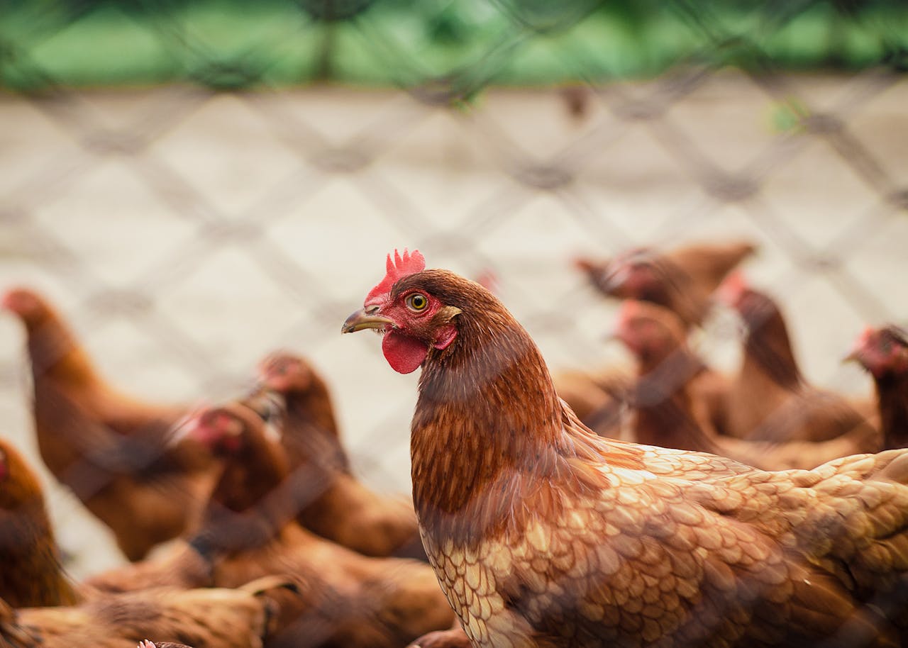
Lighting duration is a crucial factor in breeding management, which directly affects the growth, reproduction, behavior and health status of animals. Different kinds of animals have different needs for light, and scientific and reasonable arrangement of lighting duration can significantly improve breeding efficiency and animal welfare. The following are the main effects of different lighting duration on farming.
(Image source:Pexels)
1.Effect on growth performance
*Appropriate lighting duration: can promote the metabolism of animals, improve feed conversion, accelerate growth.
*Too long lighting duration: may cause animals to be overactive, consume too much energy, but affect growth.
*Too short light duration: may inhibit the animal's appetite and activity, resulting in slow growth.
2.Effect on reproductive performance
*Poultry (e.g. chickens)
Increase the lighting duration: can stimulate the gonad development of hens, improve the egg production rate. A cycle of 16 hours of lighting and 8 hours of darkness is usually used.
Reduce lighting duration: May result in a decrease in egg production or even stop egg production.
*Mammals (e.g. pigs)
Appropriate lighting duration: helps to regulate the estrus cycle of sows and improve reproductive efficiency.
Too short light duration: may delay the sow's estrus and affect reproductive performance.
3.Effect on behavior
*Regular lighting cycles: help animals develop a stable biological clock and reduce stress responses.
*Sudden changes in lighting: May cause anxiety, increased aggression, or decreased appetite in animals.
*Excessive lighting duration: May make the animal overactive, increasing the risk of fighting and injury.
4.Effect on immunity
*Appropriate lighting: can enhance the immunity of animals, reduce the incidence of disease.
*Too short lighting duration: May suppress immune system function and increase the risk of disease.
*Too long lighting duration: may lead to animal fatigue, reduced immunity.
5.Effect on feed utilization
*Appropriate lighting duration: can promote the regular feeding of animals, improve feed utilization.
*Too short lighting duration: may reduce animal feed intake, affecting growth and reproduction.
*Excessive lighting duration: May cause animals to expend excessive energy and reduce feed conversion.
6.Effect on meat quality and egg quality
*Poultry
Appropriate lighting duration: can improve eggshell quality and egg nutrients.
Too long lighting duration: may lead to eggshell thinning, egg quality decline.
*Mammal
Appropriate lighting duration: helps to improve meat quality, increase muscle fat content and taste.
Too short lighting duration: may lead to poor meat quality and insufficient fat deposition.
7.Effect on animal welfare
*Appropriate lighting duration: can improve animal comfort and happiness, reduce abnormal behavior (such as feather pecking, tail biting, etc.).
*Too short lighting duration: May cause depression and abnormal behavior in animals.
*Too long lighting duration: may make animals tired and affect their normal rest.
8.Effect on economic efficiency
*Scientific lighting management: can improve breeding efficiency, reduce feed costs and medical costs, increase economic benefits.
*Unreasonable lighting time: may lead to slow growth, low reproductive efficiency and frequent diseases, increasing breeding costs.
Conclusion
Scientific and reasonable arrangement of lighting time is the key to improve breeding efficiency and animal welfare. Different kinds of animals have different needs for light, and farmers should formulate appropriate Lighting Solutions according to the types of animals, growth stages and breeding objectives.
Xiamen Good Light Technology Ltd. is a company that specializes in poultry and livestock farming lighting solutions design and R&D, production and sales of poultry and livestock lighting products. Our latest product intelligent farming lighting system, it is not only a lighting duration control system ,but also a lighting management control system. Through accurate lighting management, it can improve the growth rate and reproductive performance of animals, improve the quality of meat and eggs, reduce the incidence of disease, and ultimately maximize economic benefits.
It is well known that chickens are highly sensitive to light and have a high perception of light color. However, do you know what effects different light colors have on poultry farming?
The blue light component with a color temperature of 5000K can effectively stimulate the appetite of broilers, increase their feed intake, and thereby promote weight gain. The red light component can enhance metabolic levels and help broilers utilize feed energy more efficiently.
3000K led poultry light is used for breeder farming. Warm white light with a color temperature of 3000K is closer to sunlight, which can better balance the ratio of red and blue light, stimulate the production of sex hormones in breeders, promote the development and maturation of the reproductive system, and is conducive to improving reproductive performance.
In the early growth stage of broilers, green light treatment can significantly enhance weight gain. Green light stimulation can increase the secretion of growth-promoting axis hormones in the later embryonic stage and early brooding stage of broilers, enhance the mitotic activity of skeletal muscle satellite cells, and up-regulate myogenic regulatory factors, thereby promoting muscle growth. In addition, green light can improve the structure of the small intestinal mucosa in broilers, promote the proliferation of intestinal gland cells and small intestinal goblet cells, enhance the efficiency of nutrient digestion and absorption, and thereby promote growth and development.
In the later growth stage of broilers, blue light can significantly increase the feed conversion rate, enabling broilers to achieve higher weight gain with the same feed intake. Blue light can stimulate the anterior pituitary gland to secrete luteinizing hormone (LH) and follicle-stimulating hormone (FSH). These two hormones respectively regulate the development of the ovaries and testicles, thereby promoting the maturation of the reproductive system. Blue light can promote the synthesis of muscle proteins and enhance the quality of meat. For instance, blue light can improve indicators such as pectoral muscle weight and leg muscle weight in broilers, and reduce the feed-to-weight gain ratio (F/G), enabling broilers to utilize feed more efficiently.
During the rearing stage of young chickens, green light irradiation should be used. However, after they reach sexual maturity and start laying eggs, red light irradiation can be switched to. Red light can promote the secretion of gonadotropins in laying hens, thereby facilitating follicular development and ovulation, and thus increasing egg production. In addition, red light can also improve the biological clock of laying hens and reduce the impact of biological clock disorder on the regularity and stability of egg production.
Ultraviolet radiation can convert 7-dehydrocholesterol in chicken skin into vitamin D3, thereby promoting the absorption of calcium in feed and ensuring bone health. Ultraviolet rays can kill harmful microorganisms in the chicken house environment and reduce the risk of disease transmission. Indoor breeding can simulate natural light through LED lighting and be regularly disinfected in combination with ultraviolet lamps.
Xiamen Good Light Technology Co., Ltd. has recently launched the Two-color LED poultry farming lighting products. They belong to the poultry growth lighting. Two light colors can be switched on one lamp. It can meet the breeding needs of different chicken breeds and at different stages. It can improve the breeding environment of chicken houses and promote the healthy growth and development of poultry. The company is committed to creating unmanned breeding and more energy-efficient, environmentally friendly and healthy closed poultry houses sustainable farming lighting.
In modern poultry farming, an increasing number of farms are adopting LED lighting systems to raise poultry. Why?
Because the poultry lighting systemis energy-saving, and it has lighting control capability and strong environmental adaptability.
What kind of LED lighting system is the most suitable for poultry farming?
First, energy conservation and high efficiency
The energy consumption of LED lights is only 1/10 that of incandescent lamps and 1/4 that of energy-saving lamps. Their lifespan can reach 30,000 to 50,000 hours.
Second, adjustable spectrum
The LED light source supports regulation of different wavelength bands such as blue light (for promoting growth), green light (for promoting growth), and red light (for enhancing reproductive performance). It can also achieve the function of gradually brightening and gradually dimming, simulating the changes of natural light to reduce the stress response of the chicken flock.
Third, environmental adaptability
LED lights have a high level of water resistance, such as IP67, and are suitable for chicken house environments with high humidity and a lot of dust. They also support high-pressure water gun cleaning, making maintenance very convenient.
Fourth, intelligent control
The modern lighting system, combined with Internet of Things technology, can automatically adjust the duration, intensity, color temperature and lighting area of the light, reducing the cost of manual intervention and increasing the economic benefits of the poultry farm.
How to find the most suitable LED lighting system for poultry farming?
HERE.
Xiamen Good Light Technology Co., Ltd. specializes in the research, production and sales of LED intelligent lighting systems. Our intelligent lighting system includes LED poultry light bubs, lighting controller and cable waterproof lampholder connecting lines. Our lights have an IP67 waterproof and dustproof rating, which enables them to adapt well to the complex environment of chicken houses.
By using our system, you can easily adjust the lighting parameters, such as the light duration, intensity, color and area of the lighting. You can manage the lighting for the breeding process, allowing the lighting to promote the healthy growth of poultry and enhance their reproductive performance. With this energy-saving and cost-effective lighting system, the annual electricity bill can be reduced by 70% to 80%. And the PI (performance index) will be increased by 10% to 20%.
It's time to use science technology to transform your farm. Act quickly!